DIY SHOCK SENSOR WITH A SPEAKER Circuit Diagram To build a Simple Shock Sensor Alarm Circuit follow the below mentioned steps: Gather all the component as mentioned in the above circuit diagram; Connect pin 1 of IC1 LM358 to anode of diode D1 and cathode of D1 to on end of buzzer and the other end of buzzer to GND.

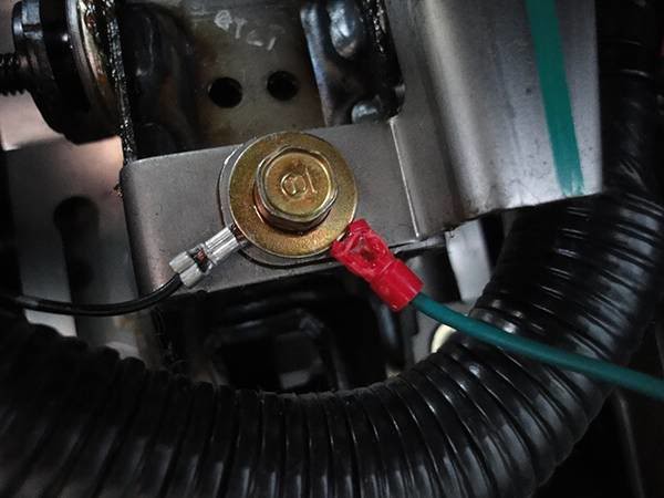
I was surprised as I though the sensor would do whatever the ultrasonic did. Perhaps the ultrasonic sensor does not power down, but somehow is simply ignored. I am unsure how a sensor in parallel on the same circuit can still set off the alarm but it does! Update The ultrasonic alarm does in fact arm even if the moonroof is left partially open.
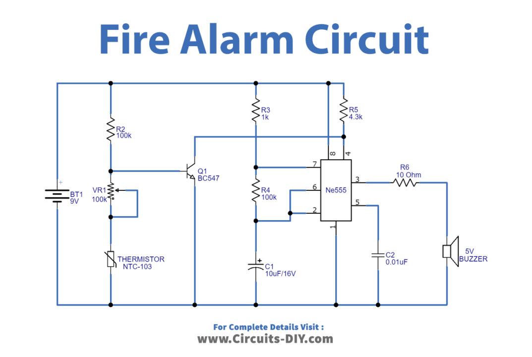
Make this Car Shock Alarm Circuit Circuit Diagram
Pendulum Style Shock Alarm. This alarm system is very useful and can be used in many different ways. It works as a sensor to detect movement and can help protect cars, big objects, houses, or other places where safety is important. By building the circuit, you can create an easy and effective way to guard against problems like theft or damage. The Shock Sensor Module, also known as a vibration sensor or shake sensor, is designed to detect sudden movements or shocks. It is commonly used in security systems, impact detection projects, and interactive installations. In this step-by-step guide, we'll show you how to set up the Shock Sensor Module with an Arduino and create projects
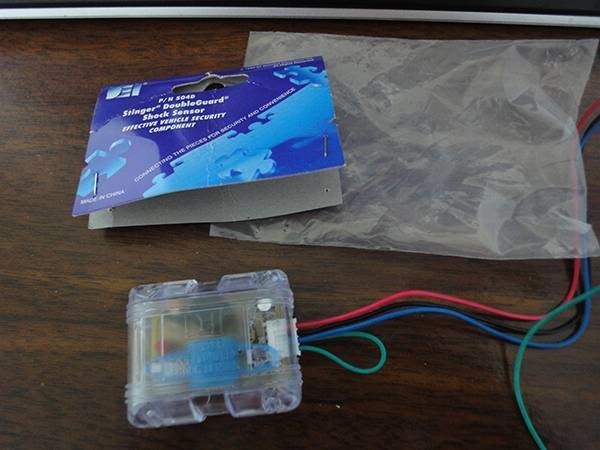
Geekcreit Shock Switch Sensor Module Circuit Alternate Shock Switch Sensor Module Circuit. If your shock sensor is configured with the 10k resistor connected between pins 1 and 2 of the module, then choose one of the following circuits. Circuit Connections to Arduino: +5V connects to the Arduino 5V pin. GND connects to the Arduino GND pin. Learn how to make a very simple wireless shock, vibration, or pressure sensing alarm that can be used for a wide range of applications, including letting you

Shock Sensor Module Arduino Tutorial Circuit Diagram
Excellent pressure sensing alarm circuit that uses a piezo wafer which has many uses!Schematic here:http://electroschematics.com/6122/pressure-sensor-alarm/C In this article I have explained a very simple and cheap car shock sensor alarm circuit which costs hardly 1/2 a dollar yet performs the actions reasonably accurately. The working Principle of the Shock alarm. The principle employed here is pretty basic, a mic is used to sense the impact, the sensed output is amplified by a transistorized