How to Create a Robot Easy RC Puppy Circuit Diagram Circuit Diagram. Making the connections for this Arduino based Self balancing Robot is pretty simple. This is a self balancing robot using Arduino and MPU6050 so we ave to interface the MPU6050 with Arduino and connect the motors though the Motor driver module. The whole set-up is powered by the 7.4V li-ion battery. A schematic is a wiring diagram that tells you where to attach wires to all the parts in your circuit. A schematic, to the uninitiated, can be a little overwhelming at first. So instead of possibly confusing you, I invented what I call a colored dot schematic. I'm willing to bet a 3 year old can understand this enough to build the circuit . . .

SCARA Robot Circuit Diagram. So, we will use an Arduino UNO board in combination with a CNC shield and four A4988 stepper drives. Although it's a robot and it seems more complicated, that's all electronics we need for this project. It's worth noting that, instead of Arduino UNO, we could also use an Arduino MEGA in combination with a

How to Build a Maze Solving Robot Using Arduino Circuit Diagram
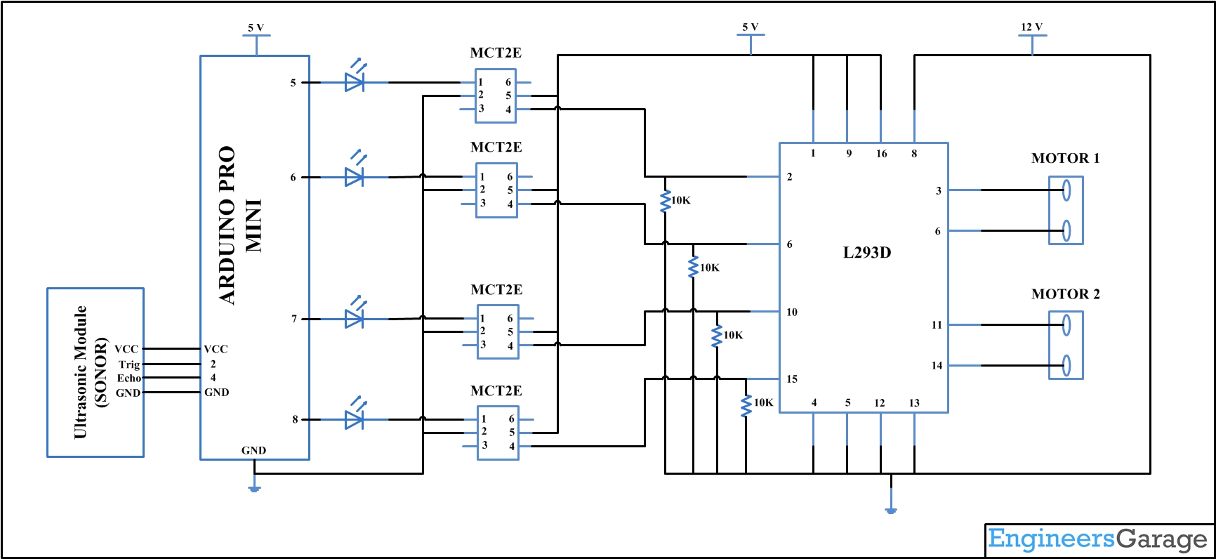
The receiver and motor driver circuit (Fig. 3) is built around Arduino UNO board (BOARD1), decoder IC HT12D (IC2), 433MHz RF receiver module (RX1), motor driver IC L293D (IC3), regulator IC 7805 (IC4) and a few discrete components. Fig. 1: Block diagram of Arduino based RF controlled robot Fig. 2: Circuit of transmitter section Arduino UNO board

Fortunately, creating a robot with circuit diagram and design isn't as daunting or time-consuming as one might think! To begin, plan out the robot's structure and what you want it to do. This step requires research on the types of materials and parts needed to create a circuit, such as a breadboard, a power source, and various sensors or In this tutorial, I'll guide you through producing this enhanced robot with new features like an OLED display, RGB LEDs, and a buzzer for melodies. Follow along as we design the circuit, assemble the PCB, and 3D print the mechanical parts. Let's bring this robot to life with motion control, Bluetooth connectivity, and customizable eye
DIY Self Balancing Robot using Arduino Circuit Diagram
Simple robot schematic diagrams are created by connecting the various components such as motors, sensors, and control systems. Control Apparatus And Method For Robot Arm Program Integrated Electronic Circuit Diagram Schematic Image 61. Diy Line Follower Robot Using 8051 Microcontroller With Circuit And Program.