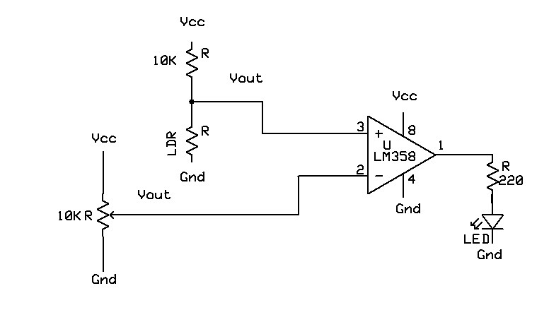
Light sensor circuit Light sensor Circuit Diagram Build a DIY light sensor circuit with a PNP transistor. Simple guide to make an LED light up in the dark, complete with steps and practical tips.

This Arduino Light sensor circuit is a simple example that shows you how to connect light sensors such as photoresistors, photodiodes, and phototransistors, to an Arduino. In this quickstart guide, you'll learn how to connect a photoresistor to an Arduino board and read out the voltage. How To Make Light Sensor CircuitDIY Light Sensor Using LDR & PhotodiodeSimple DIY ProjectsCircuit Diagram of My Every Projects will be displayed during the v Learn how light sensors work and how to create and use a simple light detector sensor with a light-dependent resistor (LDR), set resistors, and a transistor.

How To Make Light Sensor Circuit, DIY Light Sensor Using LDR ... Circuit Diagram
The light sensor circuit is a simple electrical circuit, which can be used to control the (switch on and off) electrical load appliances like lights, fans, coolers, air conditioners, street lights, etc., automatically.
We are going to build a simple Light Sensing circuit or Light Detector using LDR - a resistive light sensor, to control the ON-OFF of the system associated with respect to the intensity of light that falls on it. The light sensor circuit is one of the coolest circuits in basic electronics projects. It detects the quantity of light present in the environment and the results can be detected by the brightness of the LED. This circuit may be useful for knowing the working of LDR (Light Dependent Resistor) or Photoresistor, the working of NPN Transistor, and the impact of the sensitivity of the resistor on

DIY Light Sensor Circuit: Step Circuit Diagram
A light sensor circuit activates when light is detected by the circuit. It is a simple circuit including a photoresistor followed by a transistor. When light strikes the surface of the photoresistor, light energy is converted into an electrical signal and thus, the circuit is operational. This tutorial covered the basics of setting up an LDR light sensor, writing the code to read values, and testing the live output. Building this simple circuit and program provides a foundation for developing more complex projects involving light detection.