Lithium Battery Load Tester Circuit Diagram An electronic load could be any component in a circuit that consumes power or energy. Electronic loads are often used for power supply testing. DC electronic load is used for testing DC output power and batteries while the AC electronic load is for AC power and generators. Grab one and start testing your batteries! Do you have any other
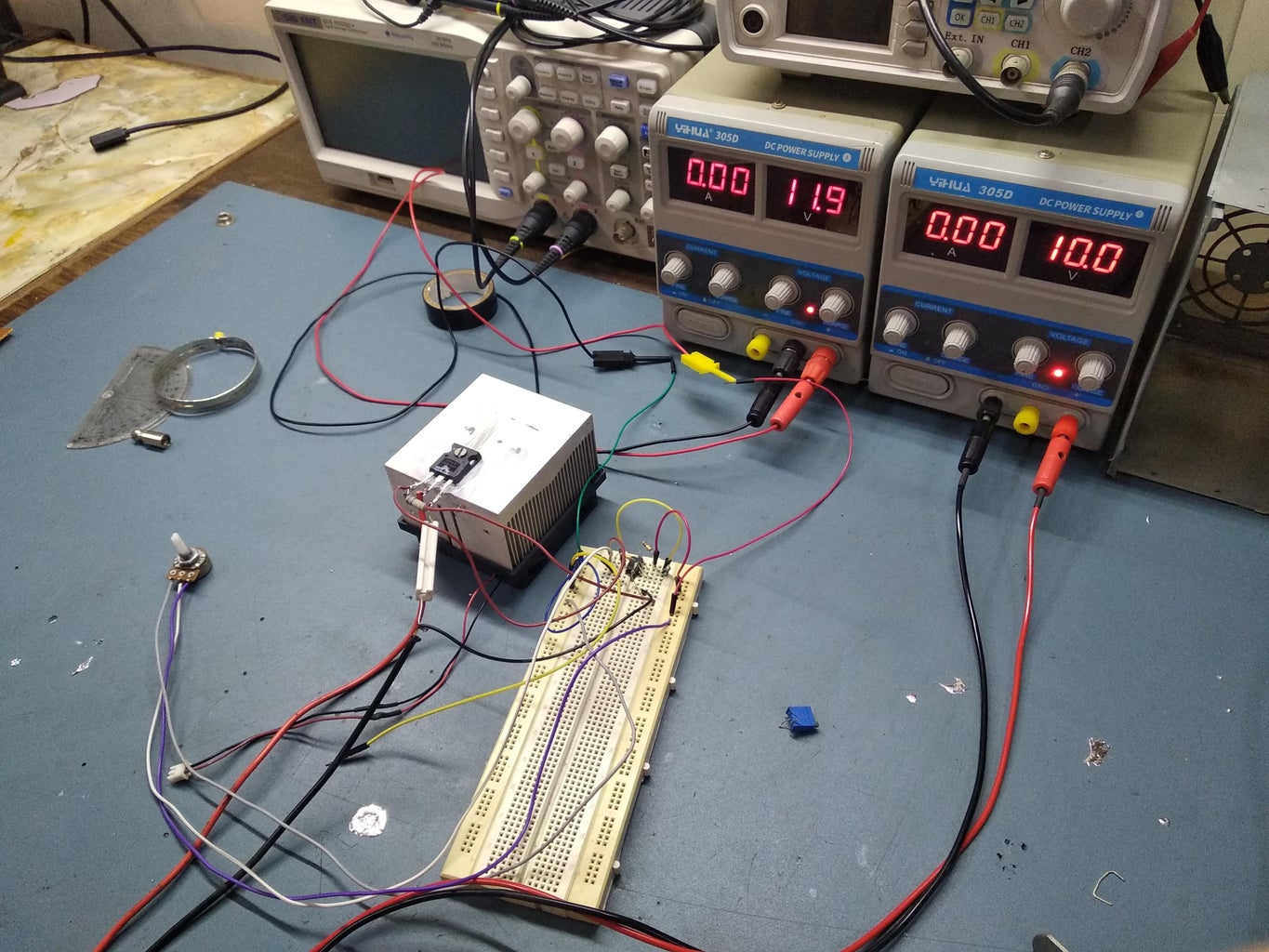
This Video is a demonstration of making and testing an Electronic load to test the Batteries and the Power Supply Units like AC to DC converter SMPS power su The principle of the circuit as shown in block diagram Figure 1. When we bring the battery that requires test the voltage in this circuit. The circuit will get voltage to compare with voltage internal the circuit. Which come from the battery 9 volts, then display with LED, If the battery still has a lot of power. By drawing a minuscule current, the voltmeter does not interfere with the circuit's performance. When testing a battery, you want to test it at certain load current. A typical rechargeable AA battery has 1.2V, so the current equals 1.2V / 330Ω = 0.0036A. Testing the battery at 3.6mA is more accurate than testing at some nano-amperes of current.

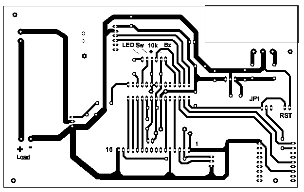
Simple Electronic DC Load Circuit Diagram
A quickly decreasing voltage indicates that the battery or batteries will have to be replaced soon. If a constant-current circuit is used for the load, the current can never too be large and there is no need to make an adjustment for the number of cells. The constant-current circuit is specially designed to work with a voltage as low as 0.9 V.

This circuit uses the popular and easy to find LM3914 IC. This IC is very simple to drive, needs no voltage regulators (it has a built in voltage regulator) and can be powered from almost every source. Description. When the test button is pressed, the Car battery voltage is feed into a high impedance voltage divider.
DIY Constant Current Dummy Load for Power Supply and Battery Testing Circuit Diagram
Circuit Debugging: Use the dummy load to simulate different load conditions on your electronic circuits, helping you identify and isolate potential issues. Calibration and Verification : Utilize the constant current load as a reference for calibrating and verifying the accuracy of other instruments, such as ammeters or power analyzers. Now we will build a circuit which can show whether the voltage that a battery is outputting is above or below a certain level. We can adjust the circuit so that any type of battery can be tested with this circuit. It would just require adjustment of the voltage. How we will build this circuit is mainly through the use of a voltage comparator IC.