Measuring Current For Dummies Circuit Diagram Design low resistance shunt resistor using a simple wire Display the dc current value on an LCD. it can be used as a digital Ammeter circuit for current measurement in electronics experiments. measure its resistance with the help of ohm meter. You can easily design .47 ohm resistor with the help of simple wire. It is a hit and trial method.
The multimeter is an indispensable tool for any electronics project, as it helps overcome countless challenges during project completion. This article will demonstrate how to create a cost-effective digital multimeter using an Arduino board and an OLED display. This multimeter is capable of measuring voltage, current, resistance, and capacitance.

How to Measure Current Using a Multimeter(AC /DC) in 6 Steps Circuit Diagram
In this step-by-step guide, we'll show you how to build a reliable and accurate meter panel that measures both voltage and current for AC circuits.By followi
For current measurement, they are connected in series with the circuit. Multimeters are ideal for general-purpose troubleshooting and diagnostics in various electronic and electrical projects. Clamp meters: Clamp meters measure current without needing to make physical contact with the conductor or interrupt the circuit. They work by clamping

DC Chapter 8: Metering Circuits Circuit Diagram
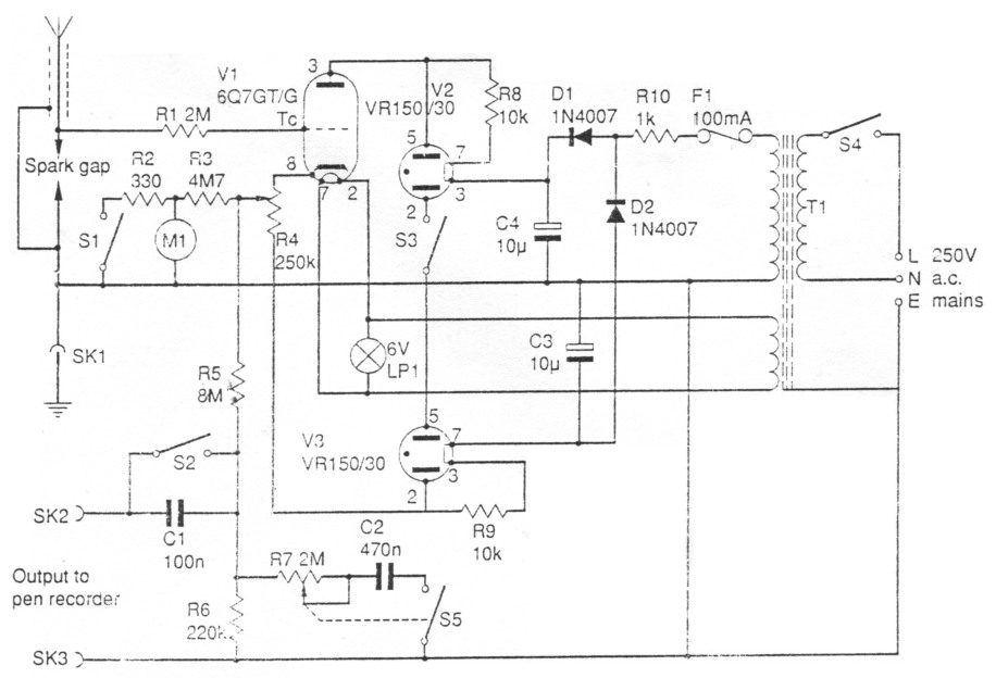
The secondary ac current is rectified and smoothed by D1 and C. The R1 and R2 shunt resistors yield a correct full scale for the meter. You may need to combine a few standard value resistors to
How to measure AC/DC current using a multimeter! To measure AC or DC current with a multimeter, set the dial to the corresponding current (AC or DC) mode and connect the meter in series with the circuit. Step 1: Insert the probes into the appropriate multimeter port. Connect the black probe to the "COM" port of the multimeter. The Micro Ampere Meter Circuit is a valuable tool for accurately measuring small electric currents typically in the microampere range. By using a combination of resistors, operational amplifiers and a current measuring device this circuit provides a reliable method for monitoring and analyzing low level currents in various electronic applications.
Build AC Power Meter Circuit Diagram
The transistors are BC640, however you may try other transistors like 8550 or 187 etc. The proposed digital voltmeter, ammeter circuit module can be effectively used with a power supply for indicating the voltage and current consumption by the connected load through the attached modules. Referring to the circuit diagram below, the 3 digit digital display module is build through the ICs CA 3162
