Quantum Computer Circuit Circuit Diagram Quantum circuit design diagrams are valuable tools for quantum algorithm design and research communication. They simplify complex quantum computations, allowing researchers and enthusiasts to visualize and analyze quantum circuits. This leads to advancements in quantum computing. Quantum vs Classical Circuits

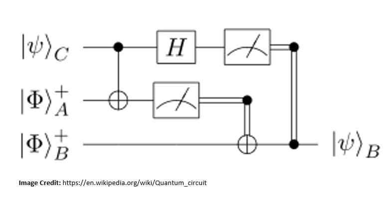
In general, quantum circuits can contain any number of qubit wires. We may also include classical bit wires, which are indicated by double lines, like in this example:. Here we have a Hadamard gate and a controlled-NOT gate on two qubits X \mathsf{X} X and Y, \mathsf{Y}, Y, just like in the previous example. We also have two classical bits, A \mathsf{A} A and B, \mathsf{B}, B, as well as two
Design of Quantum Computing Circuits Circuit Diagram
For example, it is known that a circuit of size scan be evaluated in time O(slogs) by a Turing Machine, and conversely, a Turing Machine operating in time ton length-ninputs can be converted to an n-input circuit of size O(tlogt). Here is a simple example of a circuit computing the XOR function, f(x 1;x 2) = x 1 x 2:
.png/:/cr=t:13.59%25,l:27.91%25,w:41.36%25,h:73.53%25/rs=w:365,h:365,cg:true,m)
ing design workflows and testing infrastructure. There is a wide variety of technologies under consideration for device development, and this article focuses on the current workflows surrounding quantum devices fabricated in semiconducting, superconducting, and Quantum Computing Circuits and Devices Travis S. Humble Oak Ridge National Laboratory

Quantum Computing Circuit Design: A Tutorial Circuit Diagram
A basic tutorial on designing very simple quantum circuits in Qiskit. Introduction. In a previous post I described the beginning of my learning path in Quantum Machine Learning (QML) and how I decided to use Qiskit. I think this package is the best way to start because it is simple to use and to design basic quantum circuits, visualizing and simultaing them.